Reverse
Engineering
Geo Informatics as an organization has experience in reverse engineering of design of various parts from automotive chassis and trucks, manufacturing plant components to aircraft and other special-purpose vehicles. We do both parametric and non-parametric modeling to generate 3D CAD models and subsequently generate 2D drawings from them.
Why Geo Informatics?
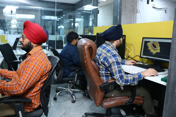
- Experience of creating 3D CAD models via the process of reverse engineering in various segments of automotive, aerospace, defense and medical devices
- History of creating CAD models and 2D drawings of about 1000 parts
- Dedicated team of Designers
- Capability of doing both Non-Parametric and Parametric Modelling
- Using multiple software such as Siemens UG/NX and Geo Magic for design
- Capability of using technology and Manpower to give an apt balance of Time, Quality and Cost
- Largest and most diverse tools available to a metrology lab for 3D scanning
REVERSE
ENGINEERING
Equipment we use for scanning for the purposes of Reverse Engineering
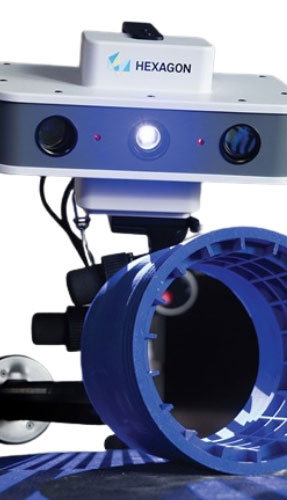
- Has a scanning accuracy of 10-30 microns depending upon the model and the part features
- Good for scanning precise small components from a range of 0 – 1m
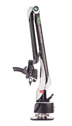
- Has a Scanning accuracy of 30 – 70 microns depending upon the machine model and the part features
- Good for scanning mid to large size components from 2m to 5m
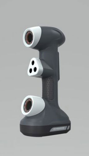
- Has a scanning accuracy of 60 microns to 100 microns depending upon machine model and part features
- Good for Scanning large sized components from 3m to 7m
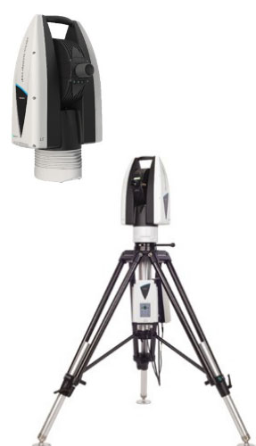
- Used to scan and probe big components up to a part size of 10m in a single shot and 80m in multiple shots
- Can give an accuracy anywhere between 0.1 mm to 1 mm depending upon the size of the parts
How is reverse engineering done?
Reverse engineering in design includes creating a CAD model from a physical part using various measurement tools and scanners
How reverse engineering is done –
- The part is received
- In most cases scanning using a 3D scanner is done to generate a point cloud data
- The point cloud data is then used to generate surfaces and hence a CAD model with accuracies as good as 0.1mm or better
- Then customer proceeds to do the design changes as he wishes on the part or use the same for manufacturing
1. Customer provides the Physical Part
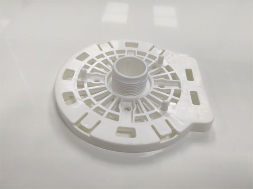
2. Scanning Process Starts
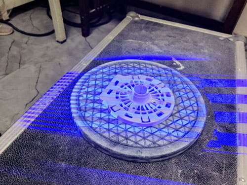
3. Scanned data is collected
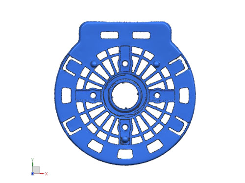
4. The Part Modelling is done
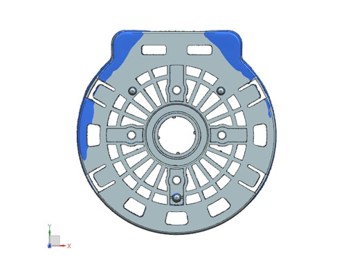
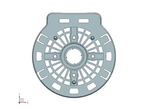
5. The CAD model is created
What is 3D Scanning? How is it relevant in design reverse engineering?
3D scanning uses a 3D scanner which maybe a Structured light scanner, an arm-basedlaser scanner or a handheld scanner
Depending upon the accuracy of the scanner chosen the scanning of a complete part can be done in as good as 20 microns
This scanned data is then used as a basis for doing design reverse engineering
How are surfaces made during reverse engineering?
After the scanned point cloud data is received by a CAD modeler, the modeler super imposes surfaces on the part mesh to generate a CAD model
Not only by this method can you get the CAD model made in a very tight tolerance but you can also make designs of the non-geometric profiles of a part such as curves which is not possible though any other method
In most cases you would be receiving the output either in IGES or STEP format
What are two different types of modelling that Geo Informatics does?
The two different types of CAD modelling Geo Informatics do is
- Parametric modelling – Parametric Modelling allows generation of CAD models using constraints and various features. This method of modelling is used in a situation such as where a family of parts need to be created. If a change is done in one section of the parts, the retrospective changes are automatically transferred to other dimensions
- Non-Parametric Modelling – Non parametric modelling or Direct modelling allows simple creation of the part from its geometric features.
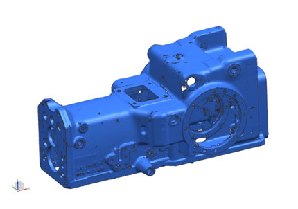
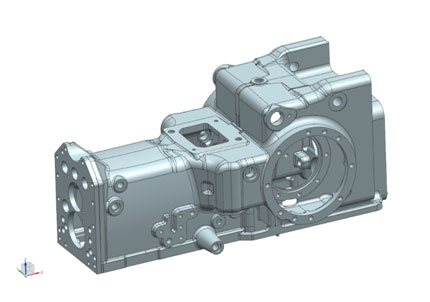
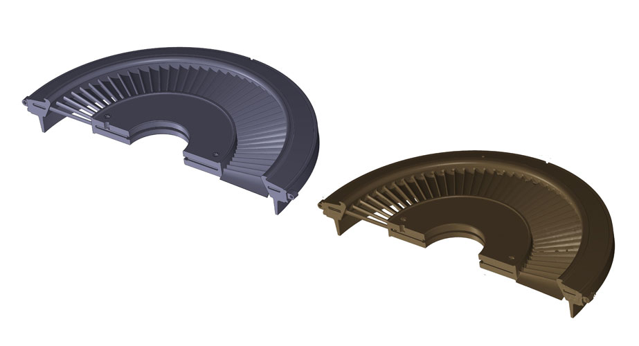
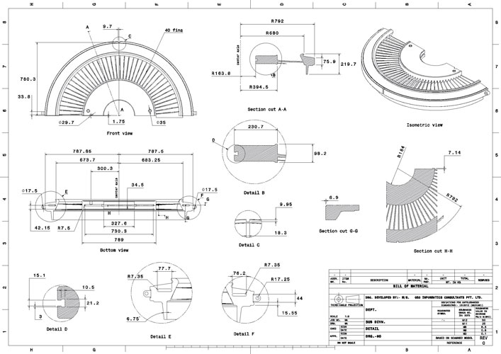
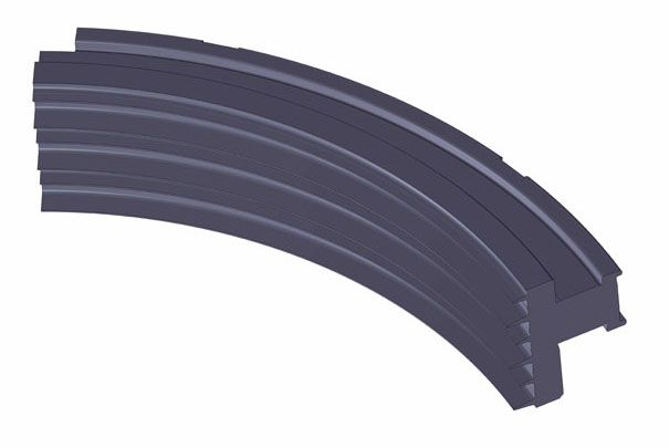
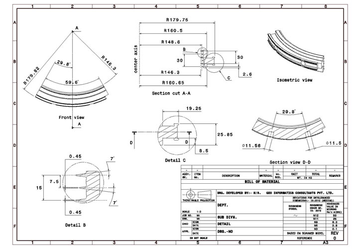
Scanned to CAD Models and 2 Drawing generation Examples
Where all are Geo Informatics labs present across the Country
Geo Informatics has designers in Cities such as
- Delhi / Ghaziabad – Near Kushambi Metro station
- Bangalore – Near Peenya Industrial Area
- Chennai
- Jamshedpur
- Pune
Frequently Asked Questions
We usually provide the customer with Output in the form of STEP or IGES files. Other formats are also possible depending upon the requirement of the customer
In the case your part size is very big we can bring one of our portable scanners to your premises for scanning and then generate the CAD model
For generating a CAD model, the cost can start from 500Rs/hour and then can go up depending upon the complexity of the part
